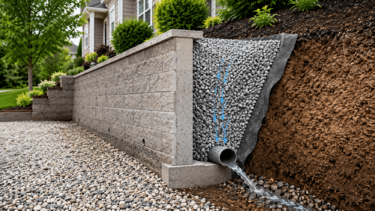
Retaining Wall Design: Calculations, Stability Checks & Worked Example
A retaining wall holds back soil where the ground level changes across a site. These walls are commonly used along roads and embankments, around basements, and in residential yards.
Depending on the site and drainage conditions, the wall may also need to resist hydrostatic water pressure.
When I am designing a retaining wall I start with inspecting site conditions. The usual sequence is as follows:
Retaining Wall Design Process
From site conditions and soil data to stability checks, structural design, and final detailing.
This guide focuses on reinforced-concrete cantilever retaining walls. Other wall systems are introduced for comparison, but the calculations, stability checks, design tool, and worked example below apply to a conventional cantilever wall.
Use the interactive design check to adjust the wall geometry, soil properties, and surcharge, then see how the overturning, sliding, and bearing checks respond.
Retaining Wall Design Check
Change the wall geometry, soil values, and surcharge. The live wall model and stability checks update instantly.
Design criteria & advanced values
Calculation details
Types of Retaining Walls
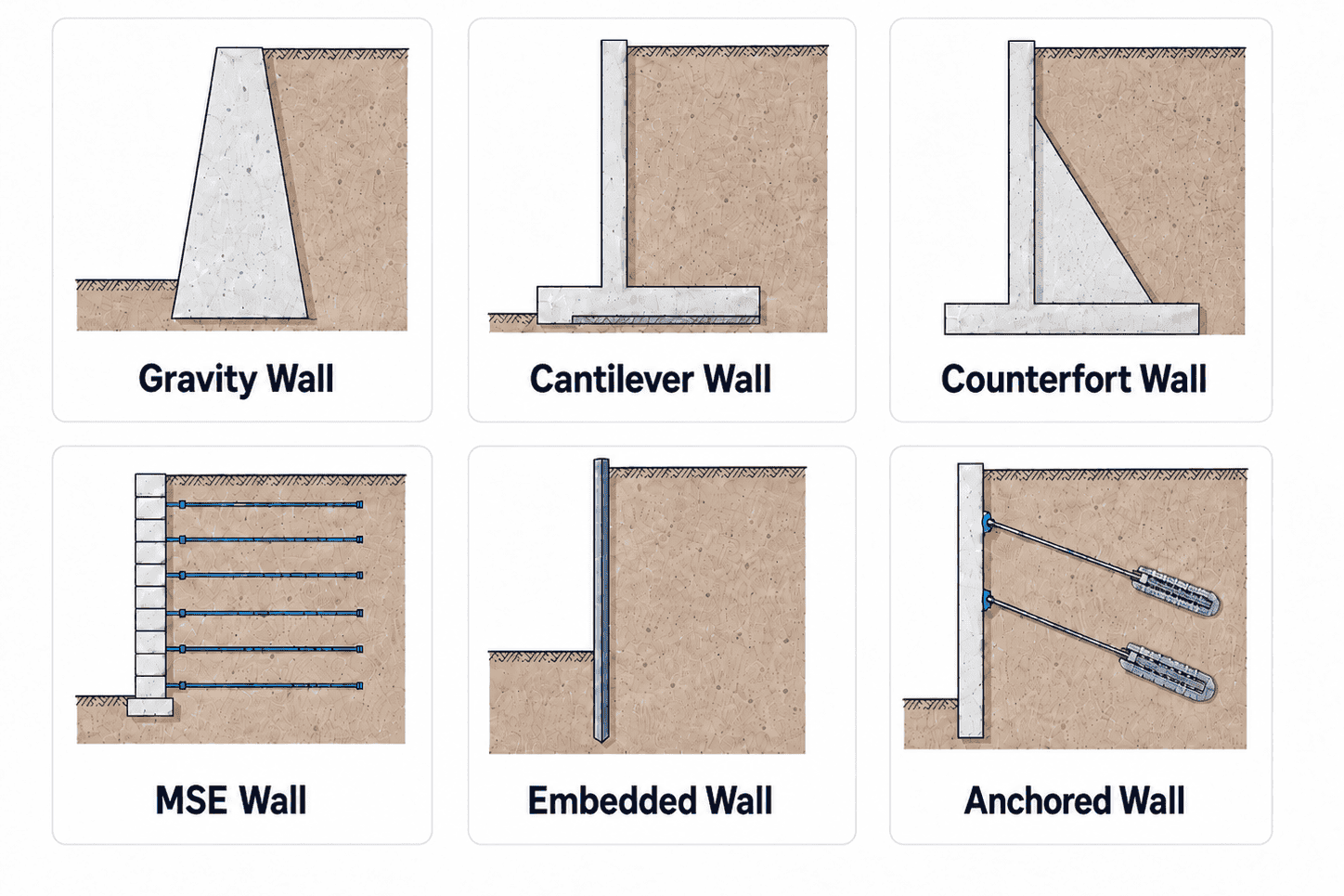
Different variables such as available space, soil conditions, construction access etc. usually determine the most practical retaining wall system. The image below shows six retaining wall types.
Gravity Retaining Wall
A gravity wall relies mainly on its own weight to resist lateral soil pressure.
Mass concrete, stone, gabion, and some modular block walls work primarily as gravity structures.
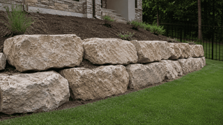
For a landscape example of a mass-type wall, see our guide to using boulders as a retaining wall
Cantilever Retaining Wall
A reinforced-concrete cantilever wall consists of a vertical stem connected to a base slab.
The part of the footing in front of the stem is the toe. The portion beneath the retained soil is the heel.
Soil above the heel contributes stabilizing weight.
This is the wall type used for the calculations in this guide.
Counterfort Retaining Wall
A counterfort wall uses reinforced-concrete webs connecting the stem and footing.
The counterforts reduce bending demands when a simple cantilever wall becomes inefficient at greater heights.
Mechanically Stabilized Earth (MSE) Wall
An MSE wall uses reinforcement layers within compacted fill. The reinforced soil mass acts as the primary retaining structure.
Its internal stability checks differ from the cantilever wall calculations covered here.
Embedded Retaining Wall
Sheet piles, soldier piles, secant piles, and similar systems develop resistance through embedment below the excavation level.
These systems require a different soil-structure model.
Anchored Retaining Wall
Anchored walls transfer part of the lateral load into tiebacks or ground anchors.
They are useful where excavation depth is large or there is not enough room for a wide footing.
If you are also planning the project budget, see our guide to the cost of a retaining wall by material, size, and labor.
Information Needed Before Design
A retaining wall calculation is only as reliable as its inputs.
I would rather use a simple calculation with defensible soil data than a sophisticated spreadsheet filled with assumptions nobody can trace.
Retained Height and Site Geometry
Establish the actual geometry first.
Check:
- retained soil height
- footing elevation
- footing embedment
- backfill slope
- ground slope in front of the wall
- nearby foundations
- roads and driveways
- property boundaries
- available heel and toe width
Do not automatically use the visible wall height as the only pressure height. Different checks can use different pressure surfaces, as the worked example later shows.
Backfill Properties
The main backfill parameters commonly include:
- soil unit weight,
γ - effective friction angle,
φ - cohesion,
c, where appropriate - soil classification
- drainage characteristics
- compaction requirements
For permanent walls, I am cautious about using soil cohesion to reduce lateral pressure unless the geotechnical recommendations specifically support it.
Foundation Soil
The soil beneath the footing affects:
- bearing resistance
- settlement
- sliding resistance
- passive resistance
- global stability
A generic soil bearing value from an online table should not be treated as project-specific foundation data.
For real work, I want the bearing and sliding parameters to come from the geotechnical recommendations or another permitted project basis.
Groundwater
Establish the design water condition before calculating loads.
I normally ask:
- Where is the groundwater table?
- Can perched water develop behind the wall?
- How will water drain?
- What happens if the drainage system becomes blocked?
Water pressure can control a wall that looks comfortable under dry-soil loading.
Surcharge Loads
A surcharge is an additional load behind the wall.
Common examples include:
- vehicles
- driveways
- nearby buildings
- storage areas
- construction equipment
- stockpiles
An 8-foot wall beside an empty yard does not have the same loading as an 8-foot wall beside a driveway.
Concrete and Reinforcing Steel
For reinforced-concrete design, establish:
- concrete compressive strength,
f'c - reinforcing steel yield strength,
fy - exposure conditions
- concrete cover
- durability requirements
ACI CODE-318-25 is ACI’s latest structural-concrete standard.
The 2024 IBC references ACI 318-19, and jurisdictions may adopt or amend different editions. Use the concrete standard legally adopted for the project.
Where Should the Values Come From?
For project work, I prefer this order:
- Project-specific geotechnical report
- Project drawings and loading information
- Applicable code provisions
- Clearly identified preliminary assumptions
Anyone reviewing the calculation should be able to identify where γ, φ, surcharge, bearing pressure, friction, and groundwater assumptions came from.
Preliminary Dimensions of a Cantilever Retaining Wall
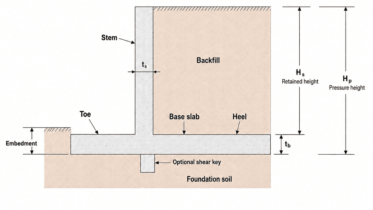
A typical cantilever wall includes:
- stem
- heel
- toe
- base slab
- optional shear key
Let:
H_s= retained height above the footingH_p= lateral pressure height used for the external stability modelB= total footing widthL_h= heel lengthL_t= toe lengtht_s= stem thicknesst_b= base slab thickness
The distinction between H_s and H_p matters.
For stem bending, lateral pressure acts over the retained height above the top of the footing.
For the external stability model used in the worked example, I treat the wall and soil above the heel as a structural wedge. Earth pressure acts on the vertical plane through the heel down to the bottom of that structural wedge.
Preliminary proportions produces a trial section.
Lateral Earth Pressure on Retaining Walls
Before calculating earth pressure, first decide how the wall can move. This determines whether active, at-rest, or passive pressure applies.
For a typical cantilever retaining wall, the sequence is: wall movement → pressure condition → pressure method → lateral force → additional loads.
Active pressure develops when the wall moves slightly away from the retained soil. A free-standing cantilever wall can usually move enough for the active condition to develop.
This is the pressure condition used in the worked example later in this guide.
At-rest pressure applies when the wall is restrained and cannot move enough to develop active pressure. A basement wall restrained by floor slabs is a common example.
Using active pressure for a restrained wall can underestimate the lateral load.
Passive pressure develops when part of the wall or footing moves into the soil. It may help resist sliding, especially in front of a footing or shear key.
I do not count passive resistance automatically. Excavation, erosion, utilities, or future grading can remove the soil providing that resistance.
Once the pressure condition is known, the next step is to determine what pressure value to use.
If the geotechnical report provides an equivalent fluid pressure (EFP), use that project-specific value. A report might state:
Active lateral earth pressure = 40 pcf EFP
EFP is not another earth-pressure theory. It is simply a convenient way to describe lateral pressure that increases with depth.
If the equivalent fluid unit weight is γeq:
The total lateral force is:
The force acts at H/3 above the bottom of the pressure diagram.
If no project-specific pressure is provided, an earth-pressure calculation may be required. For a simple wall with level, drained, cohesionless backfill, Rankine theory is commonly used.
The active earth-pressure coefficient is:
For φ = 30°:
The lateral soil pressure then increases linearly with depth:
The total active soil force is:
This force acts at H/3 above the bottom of the triangular pressure diagram.
Notice the H² term. If all other inputs stay the same, doubling the pressure height increases the soil force by four times.
Rankine is useful, but it does not fit every wall.
If the backfill slopes, wall friction is important, or the wall face is inclined, Coulomb theory or another suitable method may better represent the actual condition.
A simple way to choose is:
- Geotechnical pressure provided: use the project value.
- Simple level wall and backfill: Rankine may be suitable.
- More complex geometry or wall friction: consider Coulomb or another appropriate method.
Soil pressure is only part of the total lateral load.
After calculating it, check for surcharge, groundwater, nearby foundations, compaction pressure, and seismic loading where applicable.
Backfill compaction also matters. Heavy compaction equipment can temporarily create higher lateral pressures near the top of the wall.
The drawings should state the backfill material, lift thickness, required compaction, and equipment allowed near the wall.
Finally, compare the calculated earth pressure with the geotechnical recommendations and applicable code minimums. Use the pressure that governs the design.
Surcharge Loads Behind a Retaining Wall
Loads placed behind the wall can create additional lateral pressure. A driveway, stored material, traffic, or nearby structure are common examples.
For a uniform surcharge q, the simplified active lateral pressure is:
Unlike the triangular pressure from soil self-weight, a uniform surcharge produces a constant lateral pressure with depth.
The total horizontal force is:
The resultant acts at H/2 above the base of the pressure diagram.
Keep the soil and surcharge forces separate. They have different pressure distributions and therefore different moment arms.
Variable surcharge. A driveway or traffic load is a common example.
In the worked example later in this guide, I include the lateral pressure from a 200 psf variable driveway surcharge, but I do not credit that temporary load as additional sliding resistance over the heel.
A final design should check the required surcharge-present and surcharge-absent load cases for the adopted code and project conditions.
Nearby foundations. A footing close to the wall creates a localized stress increase in the retained soil.
Do not automatically convert every strip, line, or concentrated load into a uniform surcharge. The loading model should represent the actual geometry closely enough for the design.
Groundwater and Hydrostatic Pressure
Water pressure acts independently of the lateral pressure carried by the soil skeleton. This can become a major wall load if water builds up behind the wall.
At a depth hw below the water surface, the hydrostatic pressure is:
The pressure increases linearly with water depth. The total water force is:
The resultant acts at hw/3 above the bottom of the water-pressure diagram.
Below the groundwater table, calculate the soil pressure using effective stress and the appropriate submerged soil unit weight where required, then add the hydrostatic water pressure separately.
Drainage matters. If the design assumes drained conditions, the wall needs a reliable way to keep water pressure from building up.
A perforated pipe alone is not a complete drainage system. The wall also needs suitable drainage material, filtration, a functioning outlet, and a flow path that is unlikely to become blocked.
If those drainage provisions cannot be relied on, the design should consider the water pressure that could develop behind the wall.
Forces and External Stability
Before checking stability, draw a free-body diagram and identify the forces acting on the wall.
Typical driving forces include active soil pressure, surcharge pressure, hydrostatic pressure, and seismic earth pressure where applicable.
Stabilizing or resisting forces can include the wall self-weight, base slab weight, soil above the heel, qualifying permanent vertical loads, base friction, and passive resistance where it can be justified.
For preliminary wall, slab, or other permanent self-weight calculations, use our dead load calculator.
Get the force diagram right before doing the calculations. A missing force, wrong pressure surface, or incorrect moment arm can change the result.
Overturning
Lateral loads create an overturning moment. For a conventional cantilever wall, I normally take moments about the toe.
For the static IBC condition used in this guide:
If overturning fails, increasing the footing or heel width is often one of the first changes to investigate.
Sliding
Sliding compares the available horizontal resistance with the horizontal driving force.
For base friction:
Here, V is the stabilizing vertical load available in the governing load case. Do not automatically count every downward load.
A temporary surcharge that may be absent cannot be relied upon as permanent sliding resistance.
The footing-soil friction coefficient should represent the actual interface.
Resultant and Bearing Pressure
Once the forces and moments are known, locate the resultant beneath the footing.
For footing width B:
where xR is measured from the toe.
For full footing contact with a linear pressure distribution:
If:
the resultant lies within the middle third and the calculated pressure remains compressive across the full footing under the usual rigid-footing assumptions.
If the resultant falls outside the middle third, do not accept a negative qmin as soil tension. Use a no-tension contact model with a reduced compression zone.
Settlement and Global Stability
Passing the sliding, overturning, and bearing checks does not automatically mean the foundation will perform well.
A footing can remain below its bearing limit and still settle or rotate excessively. Settlement depends on the soil profile, footing pressure, groundwater, compressible layers, and wall geometry.
Geotechnical information is normally needed to evaluate settlement properly.
The wall can also fail as part of a larger soil mass. A deep slip surface can pass beneath the footing and behind the wall even when the local wall checks pass.
Global stability deserves closer attention when:
- the wall is on or near a slope
- weak soil layers occur below the footing
- groundwater is significant
- walls are terraced
- retained height is large
- substantial loads sit behind the wall
These conditions may require a separate slope-stability analysis.
Structural Design of the Cantilever Wall
After the external stability checks work, design the reinforced-concrete wall itself.
The stem, heel, toe, and any shear key need adequate strength, reinforcement, anchorage, crack control, and durability.
Stem
The stem behaves mainly as a vertical cantilever.
For the triangular soil-pressure component:
For a uniform surcharge:
These are service actions for the simplified pressure model. The final concrete design uses the governing factored load combinations.
The stem is then checked for flexure, shear, reinforcement requirements, anchorage, crack control, and concrete cover.
Heel and Toe
The heel extends beneath the retained soil. Its loading can include soil weight, applicable surcharge, heel self-weight, and upward foundation reaction.
Design the heel for the net load acting on it, not simply the downward weight above it.
The toe projects in front of the stem. Its loading commonly includes upward foundation reaction, footing self-weight, and any permanent vertical load above the toe where present.
The resulting bending direction determines where the main reinforcement is required.
Shear Key
A shear key can provide additional resistance when sliding controls.
It is not automatically required. If the footing already has adequate sliding resistance, a key may add excavation, concrete, reinforcement, and construction difficulty without providing much benefit.
Reinforcement and Detailing
After the member forces are known, detail the reinforcement for the actual wall geometry and governing load combinations.
Typical checks include:
- main stem reinforcement
- horizontal stem reinforcement
- heel reinforcement
- toe reinforcement
- shear-key reinforcement where used
- development length
- anchorage
- lap splices
- concrete cover
- construction joints
- crack-control reinforcement
Do not copy reinforcement from another retaining wall simply because the retained height looks similar. The reinforcement only makes sense together with the wall geometry, soil conditions, materials, and calculated actions.
Drainage and Backfill
Drainage is part of the retaining wall design, not an afterthought.
A typical drained wall may include:
- free-draining granular backfill
- perforated collector pipe
- filter aggregate or suitable geotextile
- positive outlet
- surface grading
- waterproofing where required
- weep holes where appropriate
Backfill placement matters too. The drawings should tell the contractor what material to use, how it should be placed and compacted, and what equipment can operate near the wall.
See the full guide to retaining wall drainage for drainage layers, collector pipes, outlets, and filter details.
Worked Example: 8-Foot Cantilever Retaining Wall Design
This example shows the design as an iteration. Trial 1 passes overturning and bearing but fails sliding, so I increase the heel width and check the wall again.
- level backfill
- drained condition
- cohesionless soil
- Rankine active pressure
- no passive resistance
- no seismic loading
- 200 psf variable driveway surcharge
These are example project values, not universal IBC defaults. A real design must also satisfy the governing geotechnical pressure and applicable code minimums.
Trial 1 Geometry
Trial 1 Calculations 6.5-ft base • 4.25-ft heel
The triangular soil force acts at Hp/3 = 3.0 ft above the underside of the base.
The uniform surcharge force acts at Hp/2 = 4.5 ft.
The lateral effect of the 200 psf variable surcharge is included, but the transient surcharge is not credited as stabilizing vertical load over the heel.
| Load | Weight | Centroid from toe | Resisting moment |
|---|---|---|---|
| Base slab | 975 lb/ft | 3.25 ft | 3,169 lb-ft/ft |
| Stem | 900 lb/ft | 1.875 ft | 1,688 lb-ft/ft |
| Soil above heel | 4,080 lb/ft | 4.375 ft | 17,850 lb-ft/ft |
| Total | 5,955 lb/ft | — | 22,707 lb-ft/ft |
Sliding controls Trial 1. I would not increase the assumed friction coefficient just to make the calculation pass. The footing geometry needs another iteration.
Since 0.71 < 1.08, the resultant remains within the middle third.
Sliding controls. Increase the heel and base width, then run the stability checks again.
Trial 2: Increase the Heel 7.5-ft base • 5.25-ft heel
Increase the heel from 4.25 ft to 5.25 ft. The revised footing width becomes:
The lateral soil and surcharge forces remain unchanged because Hp, the soil properties, and the surcharge have not changed.
| Quantity | Trial 2 |
|---|---|
| Base weight | 1,125 lb/ft |
| Stem weight | 900 lb/ft |
| Soil above heel | 5,040 lb/ft |
| Total vertical load, V | 7,065 lb/ft |
| Total resisting moment | 30,476 lb-ft/ft |
| Overturning FS | 4.03 PASS |
| Sliding FS | 1.59 PASS |
| Eccentricity | 0.51 ft |
| qmax | 1,324 psf |
| qmin | 560 psf |
Increasing the heel added permanent weight and moved the sliding factor from 1.34 to 1.59 without changing the assumed soil friction.
Worked Example Summary
| Check | Trial 1 | Trial 2 |
|---|---|---|
| Base width | 6.5 ft | 7.5 ft |
| Heel width | 4.25 ft | 5.25 ft |
| Soil force | 1.62 kip/ft | 1.62 kip/ft |
| Surcharge force | 0.60 kip/ft | 0.60 kip/ft |
| Overturning FS | 3.00 | 4.03 |
| Sliding FS | 1.34 FAIL | 1.59 PASS |
| Eccentricity | 0.71 ft | 0.51 ft |
| Maximum bearing pressure | 1.51 ksf | 1.32 ksf |
| Minimum bearing pressure | 0.32 ksf | 0.56 ksf |
Structural Actions for the 8-Foot Stem
External stability used the 9-ft pressure height Hp. The stem itself retains 8 ft above the base slab, so the stem actions use Hs = 8 ft.
These are unfactored actions from the simplified pressure model, not the final reinforced-concrete design values.
Final member design uses the governing structural load combinations and the concrete code adopted for the project.
Special Design Conditions
The simple level-backfill Rankine case may no longer apply. The pressure coefficient, failure geometry, and force direction can change.
Basement and other restrained walls may not move enough to develop active pressure. At-rest pressure may govern instead.
Seismic design can require additional earth-pressure and stability checks. A static retaining-wall calculation should not be treated as a seismic design.
Reinforcement Design Example for the 8-Foot Wall
The stability calculations tell us whether the wall works as a rigid body. The next step is to design the reinforced-concrete stem and footing for the factored forces they carry.
This example continues with the Trial 2 wall and checks the main flexural reinforcement and one-way shear for a 1-ft-wide strip of the stem, heel, and toe.
The calculations below demonstrate the main flexural reinforcement and one-way shear checks for this specific wall geometry. They are not a complete construction reinforcement schedule.
Final design must still address horizontal and distribution reinforcement, opposite-face reinforcement where required, development length, anchorage, splices, construction joints, crack control, cover, exposure, durability, and every governing load combination required by the code adopted for the project.
Reinforcement Design Assumptions
The cover values are assumptions for this worked example. Actual cover depends on exposure and casting conditions.
To demonstrate the member design, permanent vertical loads are factored by 1.2 and the lateral earth-pressure and variable-surcharge effects used in this example are factored by 1.6. A final project must evaluate all governing load combinations required by the adopted code.
Stem Flexural Reinforcement
The 8-ft stem acts as a vertical cantilever. From the earlier worked example, the unfactored stem-base moments are:
For the illustrative strength load case:
Effective Depth
Trial a No. 5 main bar. A No. 5 bar has a nominal diameter of 0.625 in.
Required Steel Area
For the singly reinforced 1-ft strip:
Solving for the required steel area:
Minimum Reinforcement Check
Using the 0.0018 gross-area minimum adopted for this worked example:
Flexural demand controls because 0.305 > 0.194 in²/ft.
Select the Stem Reinforcement
Provide No. 5 bars at 10 in. on center.
Under the lateral loading used here, the backfill face is the principal tension face near the base of the conventional cantilever stem.
Factored Base Pressure for Heel and Toe Design
Heel and toe design uses the net factored loading, rather than the service bearing pressures used for the earlier geotechnical stability check.
Show factored footing reaction calculation
For Trial 2, including the variable driveway surcharge over the heel for this structural load case:
The resulting linear factored footing pressure is approximately:
Heel Flexural Reinforcement
The heel acts as a cantilever extending behind the stem. Its net factored loading includes the upward foundation reaction together with the downward soil weight, slab weight, and applicable surcharge.
Integrating the net factored loading over the 5.25-ft heel gives:
For the 12-in. base slab, 3-in. assumed clear cover, and a trial No. 5 bar:
Using the 0.0018 gross-area minimum adopted for this worked example:
The adopted minimum controls.
Provide No. 5 bars at 12 in. on center:
Toe Flexural Reinforcement
The toe extends in front of the stem. Upward foundation pressure is the primary flexural load in this simplified example.
Integrating the factored net pressure over the 1.5-ft toe gives:
Using the same adopted gross-area minimum:
The adopted minimum again controls. Provide No. 5 bars at 12 in. on center.
Example Flexural Reinforcement Summary
| Member | Mu | As,req | Adopted As,min | Example Main Steel | Main Steel Location |
|---|---|---|---|---|---|
| Stem | 8.87 kip-ft/ft | 0.305 in²/ft | 0.194 in²/ft | No. 5 @ 10 in. | Backfill face |
| Heel | 8.36 kip-ft/ft | 0.218 in²/ft | 0.259 in²/ft | No. 5 @ 12 in. | Top |
| Toe | 1.89 kip-ft/ft | 0.048 in²/ft | 0.259 in²/ft | No. 5 @ 12 in. | Bottom |
One-Way Shear Check
Flexural reinforcement is only part of the member design. The stem and footing also need adequate one-way shear strength.
No shear reinforcement is included in this example. For the selected sections, use the concrete one-way shear expression:
For the normal-weight concrete and relatively shallow sections used here, λ = 1.0 and λs = 1.0. The shear strength reduction factor used in this example is φ = 0.75.
Stem Shear
For the uniform-thickness stem, check shear at the stem-to-footing interface.
Heel Shear
For the footing check, take the critical section one effective depth from the back face of the stem.
At that section, the factored foundation reaction is approximately 1.474 ksf. The factored downward soil, footing, and surcharge load over the heel is:
Integrating the net load between the critical section and the heel edge:
Toe Shear
The toe shear section is taken one effective depth from the front face of the stem toward the toe.
Integrating the net upward footing reaction between that section and the toe edge gives:
Because the toe uses the same footing thickness and No. 5 bars at 12 in. on center, its calculated concrete shear strength is the same as the heel:
For the assumptions used here, the selected No. 5 @ 10 in. stem reinforcement, No. 5 @ 12 in. heel reinforcement, and No. 5 @ 12 in. toe reinforcement satisfy the demonstrated flexural checks, while the selected 9-in. stem and 12-in. footing also satisfy the demonstrated one-way shear checks.
These values apply only to this worked example. A construction design still requires complete reinforcement detailing, development and anchorage checks, distribution reinforcement, crack-control provisions, durability requirements, and evaluation of every governing project load combination.
Common Retaining Wall Design Mistakes
A few mistakes cause a large share of retaining wall design problems. These are the ones I check first.
Select the pressure state from the expected wall movement. Restrained walls may require at-rest pressure.
A drained analysis only works if the drainage system can maintain the assumed drained condition.
Do not increase the friction coefficient or count passive resistance simply to make a sliding check pass.
The retained height used for stem design and the external stability pressure height may not be the same.
Temporary loads should not automatically be credited as permanent stabilizing weight.
Passing overturning, sliding, and bearing does not by itself prove acceptable settlement or global stability.
Preliminary dimensions are only a starting point. The calculations, site conditions, and governing design requirements determine the final wall geometry.
Construction and Drainage
The wall built in the field should match the assumptions used in the design. Before these items become difficult to inspect, confirm the founding soil, reinforcement position, concrete cover, backfill material, drainage system, and compaction procedure.
I pay particular attention to the drain outlet. A perforated pipe with nowhere to discharge is not a functioning retaining wall drainage system .
Heavy compaction equipment operating close to the wall should also be consistent with the loading assumptions used in the design.
References Used in This Example
The worked example uses conventional retaining wall mechanics together with the following code and engineering references. Final design should use the editions and requirements adopted for the actual project.
Used for minimum lateral soil loading and the retaining wall sliding and overturning stability requirements discussed in the example.
Referenced for reinforced-concrete member design, reinforcement, anchorage, detailing, and durability. Use the concrete code edition adopted by the project jurisdiction for final design.
Referenced for structural loads and load combinations applicable to final structural design.
Referenced for earth-pressure behavior, structural-wedge concepts, retaining wall stability, groundwater, and global stability.
The worked example is a preliminary educational calculation for level, drained, cohesionless backfill using Rankine active pressure.
Actual retaining walls may require project-specific geotechnical information, different earth-pressure models, groundwater analysis, seismic loading, settlement checks, or global stability analysis.
Use this guide and the calculator to understand the load path and check preliminary results. Final construction design should use the actual site conditions and the structural and geotechnical requirements adopted for the project.
FAQs
What are the main steps in retaining wall design?
Establish the site geometry, soil properties, groundwater condition, and surcharge loads first. Calculate lateral earth pressure, select trial dimensions, and check overturning, sliding, eccentricity, and bearing. Then design the concrete stem, heel, toe, and reinforcement. Settlement and global stability also need consideration where site conditions require them.
What is the difference between active and at-rest earth pressure?
Active pressure develops after the wall moves sufficiently away from the retained soil. At-rest pressure applies when the wall remains restrained and cannot deform enough to reach the active state.
How is lateral earth pressure calculated?
For simple level, drained, cohesionless backfill, Rankine theory can be used to calculate an active pressure coefficient from the soil friction angle. A geotechnical report may instead specify equivalent fluid pressure. U.S. code design must also consider the applicable minimum lateral soil loads in IBC Table 1610.1 unless project-specific geotechnical data establish otherwise.
Why Can the Pressure Height Be Greater Than the Visible Wall Height?
For the structural-wedge external stability model used in this guide, the wall and soil above the heel act together. Lateral pressure is evaluated on the vertical plane through the heel down to the base of that wedge.
The stem itself can have a smaller structural pressure height measured above the footing.
What Stability Checks Are Required for a Retaining Wall?
Typical external checks include overturning, sliding, resultant location, eccentricity, footing bearing pressure, foundation performance, and global stability where applicable.
What Is the Middle-Third Rule?
For the usual rigid-footing model, keeping the resultant within the middle third means the calculated linear bearing-pressure distribution remains compressive across the full footing width.
How Does Groundwater Affect Retaining Wall Design?
Groundwater adds hydrostatic pressure and changes effective soil stresses.
If drainage cannot reliably prevent water buildup, water pressure can substantially increase sliding and overturning demands.
When Does a Retaining Wall Need an Engineer?
Requirements vary by jurisdiction and project.
Walls supporting buildings, roads, steep slopes, significant surcharge loads, difficult soils, or substantial retained heights generally warrant structural and geotechnical engineering review. Local permitting requirements may also require engineered design.